Zephyr RTOS: Booting signed image with custom keys for MCUboot

In previous blog we have used sample key available in MCUboot repository for signing the application image. But it is strictly advised to use custom keys for production purposes or else attacker may modify the application image in flash and take control of the device. In this blog we are going to generate the custom keys and build the sample application with generated key.Before building the sample application with custom keys, a few things need to be discussed about cryptography.

Cryptography is broadly classified into two categories:

  • Symmetric Encryption
  • Asymmetric Encryption

Symmetric Encryption:

Symmetric encryption uses single key (private key) to encrypt and decrypt the message. Here sender uses private key to encrypt the message and receiver uses same private key to decrypt the message. Private key is shared between the sender and receiver.

Symmetric Algorithms: AES, Blowfish, Serpent, Twofish, 3DES and RC4.

Asymmetric Encryption

Asymmetric encryption is quite opposite to symmetric encryption, it consists of two different keys. Public and private key. Here sender uses public key to encrypt the message and receiver uses private key to decrypt the message. So public key is available to everyone and private key is kept secret with authenticated receiver.

Asymmetric Algorithms: RSA, DSA, ECC, Diffie-Hellman.

Zephyr support RSA 2048 and RSA 3072 Asymetric encryption. Here we are going to use RSA 2048 Algorithm for signing the image.

Let’s get started

cd $HOME 
cd zephyrproject/mcuboot 
Generate a key using openssl command 
openssl genrsa -out my_key.pem 2048

This command will create a file named my_key.pem which contains both private and public key.

Modify the prj.conf file to include the generated key.

vi boot/zephyr/prj.conf
CONFIG_BOOT_SIGNATURE_KEY_FILE="root-rsa-2048.pem"

change the default key from root-ras-2048.pem to my_key.pem

CONFIG_BOOT_SIGNATURE_KEY_FILE="my_key.pem"

and save the file.

Build and flash MCUboot Bootloader

west build -s boot/zephyr -b disco_l475_iot1
west flash

Once the bootloader is flashed open the device’s serial monitor by following command

minicom -b 115200 -D /dev/ttyACM0

If everyting goes right, it will display the following output.

The above image describes the bootloader is successfully flashed. Since the slot0_partition (primary partition) does not contain’s signed application image, it’s through an error message in last line.

Follow this steps to flash the sample application (signed image) with zephyr.

cd $HOME
cd zephyrproject/zephyr/samples/basic/blinky

Open the prj.conf file

vi prj.conf

And include the following line and save the file

CONFIG_BOOTLOADER_MCUBOOT=y

Build the application

cd $ZEPHYR_BASE
west build -b disco_l475_iot1 samples/basic/blinky/

Generated output can be found in the build directory

ls -l build/zephyr/zephyr.{bin, hex, elf}

Signing the builded Image with generated key

In previous blog we have used imgtool.py python script to sign the image. Here we are going to use west command to sign the image. For this we need imgtool, install the tool with pip3.

pip3 install --user imgtool

Then run the following command to generate the signed image.

west sign -t imgtool -- --key ../mcuboot/my_key.pem

This will generate the signed bin and hex in the build directory.

build/zephyr/zephyr.signed.bin
build/zephyr/zephyr.signed.hex

Flash the image

west flash --hex-file build/zephyr/zephyr.signed.hex

Open the serial monitor to check the output.

Here Bootloader chainload address offset: 0x20000, denotes the starting address of the slot0_partition. Here bootloader transfer it’s control to application image. It will blink the on board LED every second.

To check the functionality of secure booting, sign the application image with different key available in the repository.

west sign -t imgtool -- --key ../mcuboot/root-rsa-2048.pem

flash the image

west flash --hex-file build/zephyr/zephyr.signed.hex

Open the serial monitor to check the output.

MCUboot failed to boot the application image, since we are using different key for signing the application image.

Conclusion

MCUboot uses Asymmetric encryption for secure booting. Here, Bootloader uses public key and application image uses private key for signing the image.
Zephyr RTOS: Introduction to MCUboot

In the previous blog post, we have build and flashed the sample application for disco_l475_iot1 board using Zephyr RTOS. In this post we are going to build and flash the same sample application with MCUboot (Bootloader).


What is a MCUboot?

Here, MCU stands for Microcontroller and boot stands for bootloader which provides a secure firmware upgrade for 32-bit microcontroller. To build a MCUboot with Zephyr the board should have the flash partitions defined in it’s device tree. The partitions are:

  • boot_partition
  • slot0_partition
  • slot1_partition
  • scratch_partition

boot_partition

boot_partition contains the bootloader code for securely booting the application image, swapping the application image between slot0 and slot1.

slot0_partition

slot0_partition contains the application image. Once the bootloader is booted it will search the application image available in the primary partition(slot0_partition). After finding the application it will securely boot the image.

slot1_partition

This is a secordary partition, where the firmware upgrade image get stored. Zephyr application which receives the firmware upgrade via serial, bluetooth and other communication protocol, get stored in the secondary partition(slot1_partition).

Note: The size of the slot0_partition and slot1_partition should be same.

scratch_partition

This is a partition, where image get stored temporarily for swapping the image between the slot0 and slot1 partition.


Let’s get started

If you didn’t have any prior experience with Zephyr, please follow the previous blog to setup the development environment, build and flash the sample application.

Clone the MCUboot repository with the following commands:

cd $HOME

cd zephyrproject

git clone https://github.com/JuulLabs-OSS/mcuboot

cd mcuboot

Install the python dependencies by following command:

pip3 install --user -r scripts/requirements.txt

Build and flash MCUboot bootloader

Build the MCUboot bootloader with Zephyr and flash the bootloader to the board

west build -s boot/zephyr -b disco_l475_iot1

west flash

Once the bootloader is flashed open the device’s serial monitor by following command

minicom -b 115200 -D /dev/ttyACM0

If everything goes right, it will display the following output.

The above image describes the bootloader is successfully flashed. Since the slot0_partition (primary parttion) does not contain’s any signed application image, it’s through an error message in last line.

Follow this steps to flash the sample application (signed image) with zephyr.

cd $HOME

cd zephyrproject/zephyr/samples/basic/blinky

Open the prj.conf file

vi prj.conf

And include the following line and save the file

CONFIG_BOOTLOADER_MCUBOOT=y

Build the application

cd $ZEPHYR_BASE

west build -b disco_l475_iot1 samples/basic/blinky/


Generated output can be found in the build directory

build/zephyr/zephyr.{bin, hex, elf}

Signing the builded Image

Since the MCUboot is a secure bootloader we need to sign the generated application image with the private key.

cd ../mcuboot/scripts

./imgtool.py sign --key ../root-rsa-2048.pem --header-size 0x200 -S 0x6000 --align 8 --version 1.2 ../../zephyr/build/zephyr/zephyr.hex signed-zephyr.hex


Once the image is signed using imgtool.py flash the image using west.

cd ../

west flash --hex-file scripts/signed-zephyr.hex

Open the serial monitor to check the output.

Here Bootloader chainload address offset: 0x20000, denotes the starting address of the slot0_partition. Here bootloader transfer it’s control to application image. It will blink the on board LED every second.


Conclusion

In this post we build and flashed the sample application using mcuboot with available key in the repository. In this next blog post we will build and flash the image with custom keys.


Reference:

MCUboot: https://github.com/JuulLabs-OSS/mcuboot


Zephyr RTOS: Getting Started

Zephyr, a project of The Linux Foundation backed by major tech companies like Intel, Nordic Semiconductor, NXP, Linaro and much more companies developing and maintaining a small real-time operating system for connected, resource constrained devices supporting multiple architectures and targets. Zephyr is released under Open Source Apache License 2.0

This blog is a short tutorial on how to  build, flash and run the sample  application using Zephyr RTOS. Here I am using Ubuntu 18.04 and B-L475-IOT1 Development Board.


What do you need?


Setup the Zephyr Development Environment

Follow this Zephyr documentation guide to install the required linux dependencies. Since the Zephyr provides a west (meta-tool) for building application, flashing and debugging them.


Install west

pip3 install --user -U west


Clone the Zephyr Repositories

Clone all of Zephyr repositories in a new zephyrproject directory.

west init zephyrproject
cd zephyrproject
west update

Install Python Dependencies

Install python packages required by Zephyr. From the zephyrproject directory that you cloned Zephyr into:

pip3 install --user -r zephyr/scripts/requirements.txt

Build and Run an application

Go to the zephyr cloned directory

cd zephyr


Setup your build environment

source zephyr-env.sh


Before building the sample application check the environment variable are properly set by following command

printenv | grep ZEPHYR


This will print the environment variable

          ZEPHYR_TOOLCHAIN_VARIANT=zephyr

          ZEPHYR_BASE=$HOME/zephyrproject/zephyr

          ZEPHYR_SDK_INSTALL_DIR=$HOME/zephyr-sdk/

If ZEPHYR_TOOLCAIN_VARIANT and ZEPHYR_SDK_INSTALL_DIR is not set, follow the Zephyr documentaion guide to set the environment variable properly.


Build an blinky application

Build the blinky sample for ST disco_l475_iot1 board

west build -b disco_l475_iot1 samples/basic/blinky

The generated output file will be in build/zephyr/  directory. The directory contains bin, hex and elf file format.


Flash the application to a Board

west flash

Once the application is flashed it will blink the on board LED for every second.


Conclusion

In this post we build and flashed the sample blinky application for the disco_l475_iot1 board. In the next post we will build and run the sample application with Mcuboot.

Provisioning: Using Serial Download Protocol (SDP) – Part 2

In our previous post, we have explored basic details about Introduction to Provisioning and it’s needs. In this post we will narrow down our use case and experiment how it works. As mentioned in our previous post, we will use


Hardware: Phytec Phycore imx6UL/ULL SoM

Storage: eMMC


We will assume that the hardware is shipped without any software (bootloader). If the hardware is shipped with Bootloader and BSP, then we need to force the hardware to boot from Serial Download Mode (SDP) using boot switch. Refer to imx6UL/ULL datasheet and Technical Reference manual to know more about boot mode selection.


imx6UL/ULL primarily comes with 2 USB OTG controllers and to use SDP, we need to use OTG1 controller. Setup to get into SDP is,

  • Connect the USB OTG to the host machine (Raspberry PI in our case)
  • Connect debug UART to see the functional booting of the target

When in SDP mode, connecting USB OTG enumerates the Freescale imx6UL/ULL device below (seen using lsusb)

Bus 001 Device 007: ID 15a2:0080 Freescale Semiconductor, Inc.

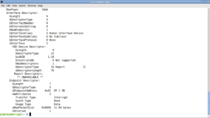
When expanded with we have,

To detail, Freescale USB device enumerated with one configuration with one Interrupt Endpoint. SDP protocol uses this USB configuration (interrupt endpoint) to communicate with the SoC and upload images over USB. This is implemented as open source imx_usb_loader. In our case, I have cloned and compiled the latest version from Github. This utility depends on libusb.


The most important part of imx USB loader is imx_usb.conf,

pi@raspberrypi:~/imx_usb_loader $ cat imx_usb.conf
#vid:pid, config_file
0x066f:0x3780, mx23_usb_work.conf
0x15a2:0x004f, mx28_usb_work.conf
0x15a2:0x0052, mx50_usb_work.conf
0x15a2:0x0054, mx6_usb_work.conf
0x15a2:0x0061, mx6_usb_work.conf
0x15a2:0x0063, mx6_usb_work.conf
0x15a2:0x0071, mx6_usb_work.conf
0x15a2:0x007d, mx6_usb_work.conf
0x15a2:0x0080, mx6ull_usb_work.conf
0x1fc9:0x0128, mx6_usb_work.conf
0x15a2:0x0076, mx7_usb_work.conf
0x1fc9:0x0126, mx7ulp_usb_work.conf
0x15a2:0x0041, mx51_usb_work.conf
0x15a2:0x004e, mx53_usb_work.conf
0x15a2:0x006a, vybrid_usb_work.conf
0x066f:0x37ff, linux_gadget.conf
0x1b67:0x4fff, mx6_usb_sdp_spl.conf
0x1b67:0x5ffe, mx6_usb_sdp_spl.conf
0x0525:0xb4a4, mx6_usb_sdp_spl.conf
0x1fc9:0x012b, mx8mq_usb_work.conf
0x1fc9:0x0134, mx8mm_usb_work.conf
0x3016:0x1000, mx8mm_usb_sdp_spl.conf

which stores the USB Vendor ID and Product ID and use respective configuration. Highlighted in RED is the Phytec’s imx6ULL SoC.

Loading U-boot bootloader image:

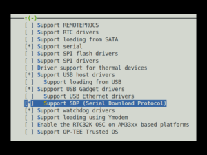
We are going to compile and load U-Boot using imx_usb_loader. To do so, we need to compile u-boot with SDP support. The mainline U-Boot version supports our board Phycore imx6UL/ULL and SDP is implemented as part of U-Boot. Please refer steps to compile u-boot and configuration option for your board/SoC in U-Boot documentation.

Configuration using: make ARCH=arm menuconfig

enable SDP in SPL and also in U-Boot and cross compile for ARM. Outcome of the compilation will be two images,

  • SPL – Secondary Program Loader (Executed directly by imx6 ROM Code)
  • U-Boot proper – Loaded by SPL

To load SPL first using imx_usb_loader,

sudo ./imx_usb ./SPL ./imx_usb.conf

which will load SPL into RAM and imx6 ROM code will start it. The next step is to load the U-Boot proper using,

sudo ./imx_usb ./u-boot-dtb.img ./imx_usb.conf

We can observe the same in imx6 targets UART Debug console,

U-Boot SPL 2019.10-00341-gffc379b42c-dirty (Oct 26 2019 - 21:54:46 +0200)
Trying to boot from USB SDP
SDP: initialize...
SDP: handle requests...
Downloading file of size 382 to 0x81000000... done
Downloading file of size 22262368 to 0x82000000... done
Downloading file of size 410113 to 0x877fffc0... done
Jumping to header at 0x877fffc0
Header Tag is not an IMX image

U-Boot 2019.10-00341-gffc379b42c-dirty (Oct 26 2019 - 21:54:46 +0200)

CPU: Freescale i.MX6ULL rev1.0 792 MHz (running at 396 MHz)
CPU: Industrial temperature grade (-40C to 105C) at 46C
Reset cause: POR
Model: Phytec phyBOARD-i.MX6ULL-Segin SBC
Board: PHYTEC phyCORE-i.MX6ULL
DRAM: 256 MiB
MMC: FSL_SDHC: 0, FSL_SDHC: 1
In: serial@2020000
Out: serial@2020000
Err: serial@2020000
Net:
Warning: ethernet@2188000 using MAC address from ROM
eth0: ethernet@2188000
Hit any key to stop autoboot: 0

Conclusion:

In this post we have viewed the basic details about SDP and it’s working when loading U-Boot using imx_usb_loader. In the next post we will explore in details about the Vendor ID and Product ID usage in U-Boot proper and relative configuration in imx_usb_load. This will help further to achieve our goal of automated flashing.